|
|
| (24 intermediate revisions by 2 users not shown) |
| Line 1: |
Line 1: |
| − | {{Redirect|Welded|the 1924 Broadway play|Eugene O'Neill}} | + | {{Infobox map |
| − | {{Featured article}}
| + | | title = Metalworks |
| − | [[File:GMAW.welding.af.ncs.jpg|thumb|Gas metal arc welding (MIG welding)]]
| + | | image = Metalworks.jpg |
| | | | |
| − | '''Welding''' is a [[fabrication (metal)|fabrication]] or [[welded sculpture|sculptural]] [[process (science)|process]] that joins materials, usually [[metal]]s or [[thermoplastic]]s, by causing [[Fusion welding|fusion]], which is distinct from lower temperature metal-joining techniques such as [[brazing]] and [[soldering]], which do not [[melting|melt]] the base metal. In addition to melting the base metal, a filler material is typically added to the joint to form a pool of molten material (the [[weld pool]]) that cools to form a joint that is usually stronger than the base material. [[Pressure]] may also be used in conjunction with [[heat]], or by itself, to produce a weld.
| + | | map_type = 5CP |
| | + | | latest_version = cp_metalworks_f4 |
| | + | | first_released = March 3, 2010 |
| | + | | last_updated = January 17, 2023 |
| | + | | developer1 = [https://steamcommunity.com/profiles/76561197977081885 Ian "Scorpio Uprising" Cuslidge] |
| | + | | official_map = No |
| | + | | download = https://dl.serveme.tf/maps/cp_metalworks_f5.bsp |
| | | | |
| − | Although less common, there are also solid state welding processes such as [[friction welding]] or [[shielded active gas welding]] in which metal does not melt.
| + | | format = [[6v6]] |
| − | | + | | in_rotation = [[ETF2L 6v6 Season 42]]<br />[[RGL Traditional Sixes Season 10|RGL 6v6 Season 10]] |
| − | Some of the best known welding methods include:
| + | }} |
| − | *[[Oxy-fuel welding]] – also known as oxyacetylene welding or oxy welding, uses fuel gases and oxygen to weld and cut metals.
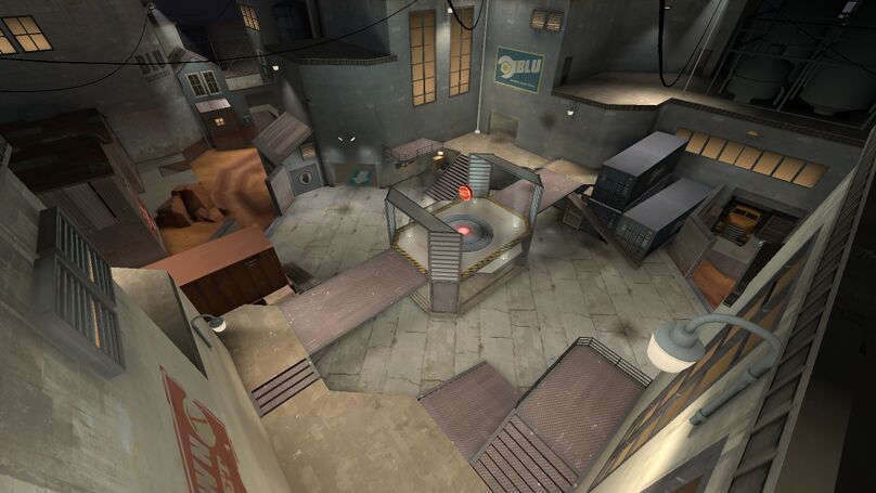
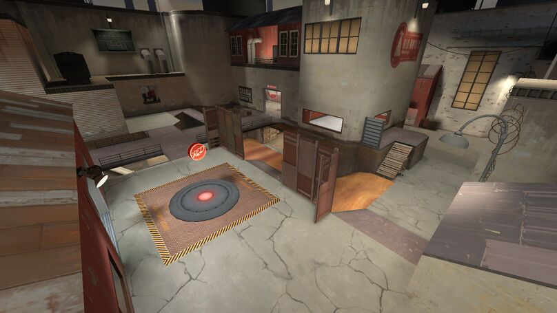
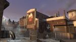
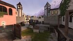
| + | '''Metalworks''' is a Control Point map made by Scorpio Uprising. It was first used competitively in [[ESEA-I Season 13|ESEA Season 13]]. It was later adopted by ETF2L as one of [[ETF2L 6v6 Season 16|Season 16]] official maps. Metalworks was made official on 7 July 2016, more than a year after it's previous revision, as a part of the long awaited Meet Your Match update.<ref name="TF2 - Meet Your Match">[http://www.teamfortress.com/meetyourmatch/ TF2 - Meet Your Match]</ref> |
| − | *[[Shielded metal arc welding]] (SMAW) – also known as "stick welding or electric welding", uses an [[electrode]] that has [[Flux (metallurgy)|flux]] around it to protect the weld puddle. The electrode holder holds the electrode as it slowly melts away. [[Slag (welding)|Slag]] protects the weld puddle from atmospheric contamination.
| |
| − | *[[Gas tungsten arc welding]] (GTAW) – also known as TIG (tungsten, inert gas), uses a non-consumable [[tungsten]] electrode to produce the weld. The weld area is protected from atmospheric contamination by an inert shielding gas such as [[argon]] or [[helium]].
| |
| − | *[[Gas metal arc welding]] (GMAW) – commonly termed MIG (metal, inert gas), uses a wire feeding gun that feeds wire at an adjustable speed and flows an argon-based shielding gas or a mix of argon and [[carbon dioxide]] (CO<sub>2</sub>) over the weld puddle to protect it from atmospheric contamination.
| |
| − | *[[Flux-cored arc welding]] (FCAW) – almost identical to MIG welding except it uses a special tubular wire filled with flux; it can be used with or without shielding gas, depending on the filler.
| |
| − | *[[Submerged arc welding]] (SAW) – uses an automatically fed consumable electrode and a blanket of granular fusible flux. The molten weld and the arc zone are protected from atmospheric contamination by being "submerged" under the flux blanket.
| |
| − | *[[Electroslag welding]] (ESW) – a highly productive, single pass welding process for thicker materials between 1 inch (25 mm) and 12 inches (300 mm) in a vertical or close to vertical position.
| |
| − | *[[Electric resistance welding]] (ERW) – a welding process that produces coalescence of laying surfaces where heat to form the weld is generated by the electrical resistance of the material. In general, an efficient method, but limited to relatively thin material.
| |
| − | | |
| − | Many different [[energy source]]s can be used for welding, including a gas [[fire|flame]], an [[electric arc]], a [[laser]], an [[electron beam welding|electron beam]], [[friction welding|friction]], and [[ultrasound]]. While often an industrial process, welding may be performed in many different environments, including in open air, [[underwater welding|under water]], and in [[outer space]]. Welding is a hazardous undertaking and precautions are required to avoid [[burn]]s, [[electric shock]], vision damage, inhalation of poisonous gases and fumes, and exposure to [[ultraviolet radiation#Human health-related effects of UV radiation|intense ultraviolet radiation]].
| |
| − | | |
| − | Until the end of the 19th century, the only welding process was [[forge welding]], which [[blacksmith]]s had used for centuries to join iron and steel by heating and hammering. [[Arc welding]] and [[oxy-fuel welding and cutting|oxyfuel welding]] were among the first processes to develop late in the century, and electric resistance welding followed soon after. Welding technology advanced quickly during the early 20th century as the world wars drove the demand for reliable and inexpensive joining methods. Following the wars, several modern welding techniques were developed, including manual methods like SMAW, now one of the most popular welding methods, as well as semi-automatic and automatic processes such as GMAW, SAW, FCAW and ESW. Developments continued with the invention of [[laser beam welding]], [[electron beam welding]], [[magnetic pulse welding]] (MPW), and [[friction stir welding]] in the latter half of the century. Today, the science continues to advance. [[Robot welding]] is commonplace in industrial settings, and researchers continue to develop new welding methods and gain greater understanding of weld quality.
| |
| − | | |
| − | ==History==
| |
| − | [[Image:QtubIronPillar.JPG|thumb|The iron pillar of Delhi]] | |
| − | | |
| − | The history of joining metals goes back several millennia. Called [[forge welding]], the earliest examples come from the [[Bronze Age|Bronze]] and [[Iron Age]]s in [[Europe]] and the [[Middle East]]. The ancient Greek historian [[Herodotus]] states in ''[[Histories (Herodotus)|The Histories]]'' of the 5th century BC that Glaucus of Chios "was the man who single-handedly invented iron welding".<ref>Herodotus. ''The Histories''. Trans. R. Waterfield. Oxford: Oxford University Press. Book One, 25.</ref> Welding was used in the construction of the [[Iron pillar of Delhi]], erected in [[Delhi]], India about 310 AD and weighing 5.4 [[metric tons]].<ref>{{harvnb|Cary|Helzer|2005|p=4}}</ref>
| |
| − | | |
| − | The [[Middle Ages]] brought advances in forge welding, in which blacksmiths pounded heated metal repeatedly until bonding occurred. In 1540, [[Vannoccio Biringuccio]] published ''[[De la pirotechnia]]'', which includes descriptions of the forging operation.<ref name="LE111">Lincoln Electric, p. 1.1-1</ref> [[Renaissance]] craftsmen were skilled in the process, and the industry continued to grow during the following centuries.<ref name="LE111" />
| |
| − | | |
| − | In 1800, [[Humphry Davy|Sir Humphry Davy]] discovered the short-pulse electrical arc and presented his results in 1801.<ref>Lincoln Electric, The Procedure Handbook Of Arc Welding 14th ed., page 1.1{{hyphen}}1<!--hyphenated page! Not a range.--></ref><ref name="Ayrton">Hertha Ayrton. ''The Electric Arc'', pp. [https://archive.org/stream/electricarc00ayrtrich#page/20/mode/2up 20], [https://archive.org/stream/electricarc00ayrtrich#page/24/mode/2up 24] and [https://archive.org/stream/electricarc00ayrtrich#page/94/mode/2up 94]. D. Van Nostrand Co., New York, 1902.</ref><ref name="anders">{{Cite journal|doi=10.1109/TPS.2003.815477 |title=Tracking down the origin of arc plasma science-II. early continuous discharges |year=2003 |author=A. Anders |journal=IEEE Transactions on Plasma Science |volume=31 |pages=1060–9 |issue=5}}</ref> In 1802, Russian scientist [[Vasily Vladimirovich Petrov|Vasily Petrov]] created the continuous electric arc,<ref name="anders" /><ref>[[Great Soviet Encyclopedia]], Article ''"Дуговой разряд"'' (eng. ''electric arc'')</ref><ref>{{Citation|last=Lazarev |first=P.P. |title=Historical essay on the 200 years of the development of natural sciences in Russia |journal=[[Physics-Uspekhi]] |volume=42 |issue=1247 |pages=1351–1361 |date=December 1999 |url=http://ufn.ru/ufn99/ufn99_12/Russian/r9912h.pdf |format=Russian |archiveurl=http://www.webcitation.org/5lmBpznUV?url=http://ufn.ru/ufn99/ufn99_12/Russian/r9912h.pdf |archivedate=2009-12-04 |doi=10.1070/PU1999v042n12ABEH000750 |deadurl=yes |df= }}</ref> and subsequently published "News of Galvanic-Voltaic Experiments" in 1803, in which he described experiments carried out in 1802. Of great importance in this work was the description of a stable arc discharge and the indication of its possible use for many applications, one being melting metals.<ref name="biog1">{{cite web |title= Encyclopedia.com. Complete Dictionary of Scientific Biography |url=http://www.encyclopedia.com/doc/1G2-2830903379.html |date=2008 |work= |publisher= Charles Scribner's Sons |accessdate=9 October 2014}}</ref> In 1808, Davy, who was unaware of Petrov's work, rediscovered the continuous electric arc.<ref name="Ayrton" /><ref name="anders" /> In 1881–82 inventors [[Nikolai Benardos]] (Russian) and [[Stanisław Olszewski]] (Polish)<ref>Nikołaj Benardos, Stanisław Olszewski, "Process of and apparatus for working metals by the direct application of the electric current" patent nr 363 320, Washington, United States Patent Office, 17 may 1887.</ref> created the first electric arc welding method known as [[carbon arc welding]] using carbon electrodes. The advances in arc welding continued with the invention of metal electrodes in the late 1800s by a Russian, [[Nikolai Slavyanov]] (1888), and an American, [[C. L. Coffin]] (1890). Around 1900, A. P. Strohmenger released a coated metal electrode in [[United Kingdom|Britain]], which gave a more stable arc. In 1905, Russian scientist Vladimir Mitkevich proposed using a three-phase electric arc for welding. In 1919, [[alternating current]] welding was invented by C. J. Holslag but did not become popular for another decade.<ref>{{harvnb|Cary|Helzer|2005|pp=5–6}}</ref>
| |
| − | | |
| − | Resistance welding was also developed during the final decades of the 19th century, with the first patents going to [[Elihu Thomson]] in 1885, who produced further advances over the next 15 years. [[Thermite welding]] was invented in 1893, and around that time another process, oxyfuel welding, became well established. [[Acetylene]] was discovered in 1836 by [[Edmund Davy]], but its use was not practical in welding until about 1900, when a suitable [[gas welding#Torch|torch]] was developed.<ref>{{harvnb|Cary|Helzer|2005|p=6}}</ref> At first, oxyfuel welding was one of the more popular welding methods due to its portability and relatively low cost. As the 20th century progressed, however, it fell out of favor for industrial applications. It was largely replaced with arc welding, as advances in metal coverings (known as [[flux (metallurgy)|flux]]) were made.<ref name="Weman26">Weman, p. 26</ref> Flux covering the electrode primarily shields the base material from impurities, but also stabilizes the arc and can add alloying components to the weld metal.<ref name='ESAB'>{{cite web |title=Lesson 3: Covered Electrodes for Welding Mild Steels |url=http://www.esabna.com/euweb/awtc/lesson3_6.htm |date= |work= |publisher= |accessdate=18 May 2017}}</ref>
| |
| − | | |
| − | [[Image:Maurzyce 2009 (0).jpg|thumb|Bridge of Maurzyce]]
| |
| − | World War I caused a major surge in the use of welding processes, with the various military powers attempting to determine which of the several new welding processes would be best. The British primarily used arc welding, even constructing a ship, the "Fullagar" with an entirely welded hull.<ref>[http://www.weldinghistory.org/whfolder/folder/wh1900.html A History of Welding]. weldinghistory.org</ref><ref>[http://www.gracesguide.co.uk/The_Engineer ''The Engineer''] (6 February 1920) p. 142</ref> Arc welding was first applied to aircraft during the war as well, as some German airplane fuselages were constructed using the process.<ref>Lincoln Electric, p. 1.1–5</ref> Also noteworthy is the first welded road bridge in the world, the [[Maurzyce Bridge]] designed by [[Stefan Bryła]] of the [[Lwów University of Technology]] in 1927, and built across the river [[Słudwia River|Słudwia]] near [[Łowicz]], Poland in 1928.<ref>{{cite web|url=http://www.weldinghistory.org/whistoryfolder/welding/wh_1900-1950.html |title=Welding Timeline 1900–1950 |last=Sapp |first=Mark E. |date=February 22, 2008 |publisher=WeldingHistory.org |accessdate=2008-04-29 |deadurl=yes |archiveurl=https://web.archive.org/web/20080803060938/http://www.weldinghistory.org/whistoryfolder/welding/wh_1900-1950.html |archivedate=August 3, 2008 }}</ref>
| |
| − | [[File:Acetylene welding on cylinder water jacket., 1918 - NARA - 530779.tif|thumb|left|170px|Acetylene welding on cylinder water jacket, US Army 1918]]
| |
| − | During the 1920s, major advances were made in welding technology, including the introduction of automatic welding in 1920, in which electrode wire was fed continuously. [[Shielding gas]] became a subject receiving much attention, as scientists attempted to protect welds from the effects of oxygen and nitrogen in the atmosphere. Porosity and brittleness were the primary problems, and the solutions that developed included the use of [[hydrogen]], [[argon]], and [[helium]] as welding atmospheres.<ref>{{harvnb|Cary|Helzer|2005|p=7}}</ref> During the following decade, further advances allowed for the welding of reactive metals like [[aluminium|aluminum]] and [[magnesium]]. This in conjunction with developments in automatic welding, alternating current, and fluxes fed a major expansion of arc welding during the 1930s and then during World War II.<ref>Lincoln Electric, p. 1.1–6</ref> In 1930, the first all-welded merchant vessel, [[M/S Carolinian]], was launched.
| |
| − | | |
| − | During the middle of the century, many new welding methods were invented. In 1930, Kyle Taylor was responsible for the release of [[stud welding]], which soon became popular in shipbuilding and construction. Submerged arc welding was invented the same year and continues to be popular today. In 1932 a Russian, [[Konstantin Khrenov]] successfully implemented the first underwater electric arc welding. [[Gas tungsten arc welding]], after decades of development, was finally perfected in 1941, and gas metal arc welding followed in 1948, allowing for fast welding of non-[[ferrous]] materials but requiring expensive shielding gases. Shielded metal arc welding was developed during the 1950s, using a flux-coated consumable electrode, and it quickly became the most popular metal arc welding process. In 1957, the flux-cored arc welding process debuted, in which the self-shielded wire electrode could be used with automatic equipment, resulting in greatly increased welding speeds, and that same year, [[plasma arc welding]] was invented. Electroslag welding was introduced in 1958, and it was followed by its cousin, [[electrogas welding]], in 1961.<ref>{{harvnb|Cary|Helzer|2005|p=9}}</ref> In 1953, the Soviet scientist N. F. Kazakov proposed the [[diffusion welding|diffusion bonding]] method.<ref>{{cite web|url=http://www.msm.cam.ac.uk/phase-trans/2005/Amir/bond.html |title=Diffusion Bonding of Materials |last=Kazakov |first=N.F |year=1985 |publisher=University of Cambridge |accessdate=2011-01-13 |deadurl=yes |archiveurl=http://www.webcitation.org/5nUYH5lQv?url=http://www.msm.cam.ac.uk/phase-trans/2005/Amir/bond.html |archivedate=2010-02-12 |df= }}</ref>
| |
| − | | |
| − | Other recent developments in welding include the 1958 breakthrough of electron beam welding, making deep and narrow welding possible through the concentrated heat source. Following the invention of the laser in 1960, laser beam welding debuted several decades later, and has proved to be especially useful in high-speed, automated welding. [[Magnetic pulse welding]] (MPW) is industrially used since 1967. [[Friction stir welding]] was invented in 1991 by Wayne Thomas at [[The Welding Institute]] (TWI, UK) and found high-quality applications all over the world.<ref>{{cite book|author=Mel Schwartz|title=Innovations in Materials Manufacturing, Fabrication, and Environmental Safety|url=https://books.google.com/books?id=rpCs0AoQOBoC&pg=PA300|accessdate=10 July 2012|date=2011|publisher=CRC Press|isbn=978-1-4200-8215-9|pages=300–}}</ref> All of these four new processes continue to be quite expensive due the high cost of the necessary equipment, and this has limited their applications.<ref>Lincoln Electric, pp. 1.1–10</ref>
| |
| − | | |
| − | ==Processes==
| |
| − | | |
| − | ===Arc===
| |
| − | {{Main article|Arc welding}}
| |
| − | [[File:Man welding a metal structure in a newly constructed house in Bengaluru, India.webm|thumb|Man welding a metal structure in a newly constructed house in Bengaluru, India]]
| |
| − | These processes use a [[welding power supply]] to create and maintain an electric arc between an electrode and the base material to melt metals at the welding point. They can use either [[direct current|direct]] (DC) or alternating (AC) current, and consumable or non-consumable [[electrode]]s. The welding region is sometimes protected by some type of inert or semi-[[inert gas]], known as a shielding gas, and filler material is sometimes used as well.
| |
| − | | |
| − | ====Power supplies====
| |
| − | To supply the electrical power necessary for arc welding processes, a variety of different power supplies can be used. The most common welding power supplies are constant [[electrical current|current]] power supplies and constant [[voltage]] power supplies. In arc welding, the length of the arc is directly related to the voltage, and the amount of heat input is related to the current. Constant current power supplies are most often used for manual welding processes such as gas tungsten arc welding and shielded metal arc welding, because they maintain a relatively constant current even as the voltage varies. This is important because in manual welding, it can be difficult to hold the electrode perfectly steady, and as a result, the arc length and thus voltage tend to fluctuate. Constant voltage power supplies hold the voltage constant and vary the current, and as a result, are most often used for automated welding processes such as gas metal arc welding, flux cored arc welding, and submerged arc welding. In these processes, arc length is kept constant, since any fluctuation in the distance between the wire and the base material is quickly rectified by a large change in current. For example, if the wire and the base material get too close, the current will rapidly increase, which in turn causes the heat to increase and the tip of the wire to melt, returning it to its original separation distance.<ref>{{harvnb|Cary|Helzer|2005|pp=246–249}}</ref>
| |
| − | | |
| − | The type of current used plays an important role in arc welding. Consumable electrode processes such as shielded metal arc welding and gas metal arc welding generally use direct current, but the electrode can be charged either positively or negatively. In welding, the positively charged [[anode]] will have a greater heat concentration, and as a result, changing the polarity of the electrode affects weld properties. If the electrode is positively charged, the base metal will be hotter, increasing weld penetration and welding speed. Alternatively, a negatively charged electrode results in more shallow welds.<ref>Kalpakjian and Schmid, p. 780</ref> Nonconsumable electrode processes, such as gas tungsten arc welding, can use either type of direct current, as well as alternating current. However, with direct current, because the electrode only creates the arc and does not provide filler material, a positively charged electrode causes shallow welds, while a negatively charged electrode makes deeper welds.<ref>Lincoln Electric, p. 5.4–5</ref> Alternating current rapidly moves between these two, resulting in medium-penetration welds. One disadvantage of AC, the fact that the arc must be re-ignited after every zero crossing, has been addressed with the invention of special power units that produce a [[square wave]] pattern instead of the normal [[sine wave]], making rapid zero crossings possible and minimizing the effects of the problem.<ref>Weman, p. 16</ref>
| |
| − | | |
| − | ====Processes====
| |
| − | One of the most common types of arc welding is [[shielded metal arc welding]] (SMAW);<ref name="Weman63">Weman, p. 63</ref> it is also known as manual metal arc welding (MMA) or stick welding. Electric current is used to strike an arc between the base material and consumable electrode rod, which is made of filler material (typically steel) and is covered with a flux that protects the weld area from [[redox|oxidation]] and contamination by producing [[carbon dioxide]] (CO<sub>2</sub>) gas during the welding process. The electrode core itself acts as filler material, making a separate filler unnecessary.<ref name="Weman63" />
| |
| − | | |
| − | [[Image:US Navy 090114-N-9704L-004 Hull Technician Fireman John Hansen lays beads for welding qualifications.jpg|thumb|left|Shielded metal arc welding]]
| |
| − | | |
| − | The process is versatile and can be performed with relatively inexpensive equipment, making it well suited to shop jobs and field work.<ref name="Weman63" /><ref name="Cary103">{{harvnb|Cary|Helzer|2005|p=103}}</ref> An operator can become reasonably proficient with a modest amount of training and can achieve mastery with experience. Weld times are rather slow, since the consumable electrodes must be frequently replaced and because slag, the residue from the flux, must be chipped away after welding.<ref name="Weman63" /> Furthermore, the process is generally limited to welding ferrous materials, though special electrodes have made possible the welding of [[cast iron]], [[nickel]], aluminum, [[copper]], and other metals.<ref name="Cary103" />
| |
| − | [[Image:SMAW area diagram.svg|thumb|right|Diagram of arc and weld area, in shielded metal arc welding.
| |
| − | <br />
| |
| − | 1. Coating Flow<br />
| |
| − | 2. Rod<br />
| |
| − | 3. Shield Gas<br />
| |
| − | 4. Fusion<br />
| |
| − | 5. Base metal<br />
| |
| − | 6. Weld metal<br />
| |
| − | 7. Solidified Slag
| |
| − | ]]
| |
| − | | |
| − | [[Gas metal arc welding]] (GMAW), also known as metal inert gas or MIG welding, is a semi-automatic or automatic process that uses a continuous wire feed as an electrode and an inert or semi-inert gas mixture to protect the weld from contamination. Since the electrode is continuous, welding speeds are greater for GMAW than for SMAW.<ref name="LE5.43">Lincoln Electric, p. 5.4-3</ref>
| |
| − | | |
| − | A related process, [[flux-cored arc welding]] (FCAW), uses similar equipment but uses wire consisting of a steel electrode surrounding a powder fill material. This cored wire is more expensive than the standard solid wire and can generate fumes and/or slag, but it permits even higher welding speed and greater metal penetration.<ref>Weman, p. 53</ref>
| |
| − | | |
| − | [[Gas tungsten arc welding]] (GTAW), or tungsten inert gas (TIG) welding, is a manual welding process that uses a nonconsumable [[tungsten]] electrode, an inert or semi-inert gas mixture, and a separate filler material.<ref name="Weman31">Weman, p. 31</ref> Especially useful for welding thin materials, this method is characterized by a stable arc and high quality welds, but it requires significant operator skill and can only be accomplished at relatively low speeds.<ref name="Weman31" />
| |
| − | | |
| − | GTAW can be used on nearly all weldable metals, though it is most often applied to [[stainless steel]] and light metals. It is often used when quality welds are extremely important, such as in [[bicycle]], aircraft and naval applications.<ref name="Weman31" /> A related process, plasma arc welding, also uses a tungsten electrode but uses plasma gas to make the arc. The arc is more concentrated than the GTAW arc, making transverse control more critical and thus generally restricting the technique to a mechanized process. Because of its stable current, the method can be used on a wider range of material thicknesses than can the GTAW process and it is much faster. It can be applied to all of the same materials as GTAW except magnesium, and automated welding of stainless steel is one important application of the process. A variation of the process is [[plasma cutting]], an efficient steel cutting process.<ref>Weman, pp. 37–38</ref>
| |
| − | | |
| − | [[Submerged arc welding]] (SAW) is a high-productivity welding method in which the arc is struck beneath a covering layer of flux. This increases arc quality, since contaminants in the atmosphere are blocked by the flux. The slag that forms on the weld generally comes off by itself, and combined with the use of a continuous wire feed, the weld deposition rate is high. Working conditions are much improved over other arc welding processes, since the flux hides the arc and almost no smoke is produced. The process is commonly used in industry, especially for large products and in the manufacture of welded pressure vessels.<ref>Weman, p. 68</ref> Other arc welding processes include [[atomic hydrogen welding]], [[electroslag welding]], [[electrogas welding]], and [[stud arc welding]].<ref>Weman, pp. 93–94</ref>
| |
| − | | |
| − | ===Gas welding===
| |
| − | {{main article|Oxy-fuel welding and cutting}}
| |
| − | | |
| − | The most common gas welding process is oxyfuel welding,<ref name="Weman26" /> also known as oxyacetylene welding. It is one of the oldest and most versatile welding processes, but in recent years it has become less popular in industrial applications. It is still widely used for welding pipes and tubes, as well as repair work.<ref name="Weman26" />
| |
| − | | |
| − | The equipment is relatively inexpensive and simple, generally employing the combustion of acetylene in [[oxygen]] to produce a welding flame temperature of about 3100 °C.<ref name="Weman26" /> The flame, since it is less concentrated than an electric arc, causes slower weld cooling, which can lead to greater residual stresses and weld distortion, though it eases the welding of high alloy steels. A similar process, generally called oxyfuel cutting, is used to cut metals.<ref name="Weman26" />
| |
| − | | |
| − | ===Resistance===
| |
| − | {{Main article|Resistance welding}}
| |
| − | | |
| − | Resistance welding involves the generation of heat by passing current through the resistance caused by the contact between two or more metal surfaces. Small pools of molten metal are formed at the weld area as high current (1000–100,000 [[Ampere|A]]) is passed through the metal.<ref name="Weman8084">Weman, pp. 80–84</ref> In general, resistance welding methods are efficient and cause little pollution, but their applications are somewhat limited and the equipment cost can be high.<ref name="Weman8084" />
| |
| − | | |
| − | [[Image:Spot welder.miller.triddle.jpg|thumb|Spot welder]]
| |
| − | [[Spot welding]] is a popular resistance welding method used to join overlapping metal sheets of up to 3 mm thick.<ref name="Weman8084" /> Two electrodes are simultaneously used to clamp the metal sheets together and to pass current through the sheets. The advantages of the method include [[efficient energy use]], limited workpiece deformation, high production rates, easy automation, and no required filler materials. Weld strength is significantly lower than with other welding methods, making the process suitable for only certain applications. It is used extensively in the automotive industry—ordinary cars can have several thousand spot welds made by [[industrial robot]]s. A specialized process, called [[shot welding]], can be used to spot weld stainless steel.<ref name="Weman8084" />
| |
| − | | |
| − | Like spot welding, [[seam welding]] relies on two electrodes to apply pressure and current to join metal sheets. However, instead of pointed electrodes, wheel-shaped electrodes roll along and often feed the workpiece, making it possible to make long continuous welds. In the past, this process was used in the manufacture of beverage cans, but now its uses are more limited.<ref name="Weman8084" /> Other resistance welding methods include [[butt welding]],<ref>{{Cite book|author = John Jernberg| title = Forging| page = 26| publisher = American Technical society| year = 1919| url = https://books.google.com/books?id=-ksxAAAAMAAJ&pg=PA26}}</ref> [[flash welding]], [[projection welding]], and [[upset welding]].<ref name="Weman8084" />
| |
| − | | |
| − | ===Energy beam===
| |
| − | Energy beam welding methods, namely [[laser beam welding]] and [[electron beam welding]], are relatively new processes that have become quite popular in high production applications.<!--Reference is at the end of the paragraph--> The two processes are quite similar, differing most notably in their source of power. Laser beam welding employs a highly focused laser beam, while electron beam welding is done in a vacuum and uses an electron beam. Both have a very high energy density, making deep weld penetration possible and minimizing the size of the weld area. Both processes are extremely fast, and are easily automated, making them highly productive. The primary disadvantages are their very high equipment costs (though these are decreasing) and a susceptibility to thermal cracking.<!--Reference at the end of the paragraph--> Developments in this area include [[laser-hybrid welding]], which uses principles from both laser beam welding and arc welding for even better weld properties, [[cladding (metalworking)|laser cladding]], and [[x-ray welding]].<ref>Weman, pp. 95–101</ref>
| |
| − | | |
| − | ===Solid-state===
| |
| − | [[File:Solid-state welding processes - AWS A3.0 2001.svg|thumb|300px|right|Solid-state welding processes [[classification chart]]<ref>AWS A3.0:2001, Standard Welding Terms and Definitions Including Terms for Adhesive Bonding, Brazing, Soldering, Thermal Cutting, and Thermal Spraying, American Welding Society (2001), p. 117. {{ISBN|0-87171-624-0}}</ref>]]
| |
| − | Like the first welding process, forge welding, some modern welding methods do not involve the melting of the materials being joined. One of the most popular, [[ultrasonic welding]], is used to connect thin sheets or wires made of metal or thermoplastic by vibrating them at high frequency and under high pressure.<ref name="Weman8990">Weman, pp. 89–90</ref> The equipment and methods involved are similar to that of resistance welding, but instead of electric current, vibration provides energy input. Welding metals with this process does not involve melting the materials; instead, the weld is formed by introducing mechanical vibrations horizontally under pressure. When welding plastics, the materials should have similar melting temperatures, and the vibrations are introduced vertically. Ultrasonic welding is commonly used for making electrical connections out of aluminum or copper, and it is also a very common polymer welding process.<ref name="Weman8990" />
| |
| − | | |
| − | Another common process, [[explosion welding]], involves the joining of materials by pushing them together under extremely high pressure. The energy from the impact plasticizes the materials, forming a weld, even though only a limited amount of heat is generated. The process is commonly used for welding dissimilar materials, such as the welding of aluminum with steel in ship hulls or compound plates.<ref name="Weman8990" /> Other solid-state welding processes include [[friction welding]] (including [[friction stir welding]]),<ref name="NZ">Stephan Kallee (August 2006) [http://www.twi.co.uk/content/spswkaug2006.html "NZ Fabricators begin to use Friction Stir Welding to produce aluminium components and panels"] {{webarchive |url=https://web.archive.org/web/20100316134257/http://www.twi.co.uk/content/spswkaug2006.html |date=March 16, 2010 }}. ''New Zealand Engineering News''.</ref> [[magnetic pulse welding]],<ref name="EMPT">Stephan Kallee et al. (2010) ''[http://www.msm.cam.ac.uk/phase-trans/2010/IPM.pdf Industrialisation of Electromagnetic Pulse Technology (EMPT) in India]'' 38th Anniversary Issue of PURCHASE India.</ref> co-extrusion welding, [[cold welding]], [[diffusion bonding]], [[exothermic welding]], [[high frequency welding]], hot pressure welding, [[induction welding]], and [[Cladding (metalworking)|roll welding]].<ref name="Weman8990" />
| |
| − | | |
| − | ==Geometry==<!-- "Butt joint (welding)" redirects here -->
| |
| − | {{Main article|Welding joint}}
| |
| − | [[Image:Common Joint Types ZP.svg|left|thumb|Common welding joint types – (1) Square butt joint, (2) V butt joint, (3) Lap joint, (4) T-joint]]
| |
| − | | |
| − | Welds can be geometrically prepared in many different ways. The five basic types of weld joints are the butt joint, lap joint, corner joint, edge joint, and T-joint (a variant of this last is the [[cruciform joint]]). Other variations exist as well—for example, double-V preparation joints are characterized by the two pieces of material each tapering to a single center point at one-half their height. Single-U and double-U preparation joints are also fairly common—instead of having straight edges like the single-V and double-V preparation joints, they are curved, forming the shape of a U. Lap joints are also commonly more than two pieces thick—depending on the process used and the thickness of the material, many pieces can be welded together in a lap joint geometry.<ref>{{Cite book
| |
| − | | last = Hicks
| |
| − | | first = John
| |
| − | | year = 1999
| |
| − | | title = Welded Joint Design
| |
| − | | location = [[New York City|New York]]
| |
| − | | publisher = Industrial Press
| |
| − | | isbn = 0-8311-3130-6 | pages=52–55
| |
| − | }}</ref>
| |
| − | | |
| − | Many welding processes require the use of a particular joint design; for example, resistance spot welding, laser beam welding, and electron beam welding are most frequently performed on lap joints. Other welding methods, like shielded metal arc welding, are extremely versatile and can weld virtually any type of joint. Some processes can also be used to make multipass welds, in which one weld is allowed to cool, and then another weld is performed on top of it. This allows for the welding of thick sections arranged in a single-V preparation joint, for example.<ref>{{harvnb|Cary|Helzer|2005|pp=19, 103, 206}}</ref>
| |
| − | | |
| − | [[Image:Welded butt joint x-section.svg|thumb|The cross-section of a welded butt joint, with the darkest gray representing the weld or fusion zone, the medium gray the heat-affected zone, and the lightest gray the base material.]]
| |
| − | After welding, a number of distinct regions can be identified in the weld area. The weld itself is called the fusion zone—more specifically, it is where the filler metal was laid during the welding process. The properties of the fusion zone depend primarily on the filler metal used, and its compatibility with the base materials. It is surrounded by the [[heat-affected zone]], the area that had its microstructure and properties altered by the weld. These properties depend on the base material's behavior when subjected to heat. The metal in this area is often weaker than both the base material and the fusion zone, and is also where residual stresses are found.<ref>{{harvnb|Cary|Helzer|2005|pp=401–404}}</ref>
| |
| − | | |
| − | ==Quality==
| |
| − | {{main article|Weld quality assurance}}
| |
| − | [[Image:Pipe root weld with HAZ.jpg|thumb|The blue area results from oxidation at a corresponding temperature of {{convert|600|°F|°C|abbr=on}}. This is an accurate way to identify temperature, but does not represent the HAZ width. The HAZ is the narrow area that immediately surrounds the welded base metal.]]
| |
| − | | |
| − | Many distinct factors influence the strength of welds and the material around them, including the welding method, the amount and concentration of energy input, the [[weldability]] of the base material, filler material, and flux material, the design of the joint, and the interactions between all these factors.<ref name="Weman6062">Weman, pp. 60–62</ref> To test the quality of a weld, either [[destructive testing|destructive]] or [[nondestructive testing]] methods are commonly used to verify that welds are free of defects, have acceptable levels of residual stresses and distortion, and have acceptable heat-affected zone (HAZ) properties. Types of [[welding defect]]s include cracks, distortion, gas inclusions (porosity), non-metallic inclusions, lack of fusion, incomplete penetration, lamellar tearing, and undercutting.
| |
| − | | |
| − | The metalworking industry has instituted [[List of welding codes|specifications and codes]] to guide [[welders]], [[weld inspectors]], [[engineers]], managers, and property owners in proper welding technique, design of welds, how to judge the quality of [[Welding Procedure Specification]], how to judge the skill of the person performing the weld, and how to ensure the quality of a welding job.<ref name="Weman6062" /> Methods such as [[visual inspection]], [[radiography]], [[ultrasonic testing]], [[phased-array ultrasonics]], [[dye penetrant inspection]], [[magnetic particle inspection]], or [[industrial computed tomography]] can help with detection and analysis of certain defects.
| |
| − | | |
| − | ===Heat-affected zone===
| |
| − | The heat-affected zone (HAZ) is a ring surrounding the weld in which the temperature of the welding process, combined with the stresses of uneven heating and cooling, alter the [[heat-treatment]] properties of the alloy. The effects of welding on the material surrounding the weld can be detrimental—depending on the materials used and the heat input of the welding process used, the HAZ can be of varying size and strength. The [[thermal diffusivity]] of the base material plays a large role—if the diffusivity is high, the material cooling rate is high and the HAZ is relatively small. Conversely, a low diffusivity leads to slower cooling and a larger HAZ. The amount of heat injected by the welding process plays an important role as well, as processes like oxyacetylene welding have an unconcentrated heat input and increase the size of the HAZ. Processes like laser beam welding give a highly concentrated, limited amount of heat, resulting in a small HAZ. Arc welding falls between these two extremes, with the individual processes varying somewhat in heat input.<ref>Lincoln Electric, pp. 6.1-5–6.1–6</ref><ref>Kalpakjian and Schmid, pp. 821–22</ref> To calculate the heat input for arc welding procedures, the following formula can be used:
| |
| − | | |
| − | :<math>Q = \left(\frac{V \times I \times 60}{S \times 1000} \right) \times
| |
| − | \mathit{Efficiency}</math>
| |
| | | | |
| − | where ''Q'' = heat input ([[kilojoule|kJ]]/mm), ''V'' = voltage ([[Volt|V]]), ''I'' = current (A), and ''S'' = welding speed (mm/min). The efficiency is dependent on the welding process used, with shielded metal arc welding having a value of 0.75, gas metal arc welding and submerged arc welding, 0.9, and gas tungsten arc welding, 0.8.<ref>Weman, p. 5</ref> Methods of alleviating the stresses and brittleness created in the HAZ include [[Heat treating#Stress relieving|stress relieving]] and [[Tempering (metallurgy)#Welded steel|tempering]].<ref>''How To Weld'' By Todd Bridigum - Motorbook 2008 Page 37</ref>
| + | The map is based on a earlier map map also made by Scorpio Uprising called resonance. |
| | | | |
| − | ===Lifetime extension with aftertreatment methods===
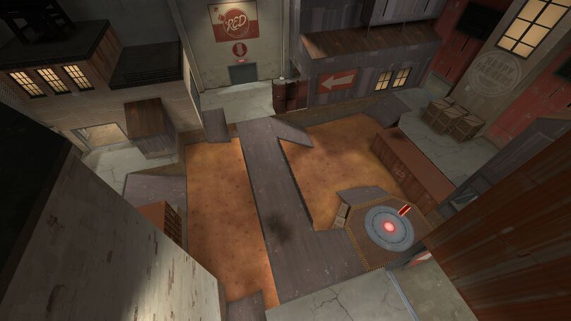
| + | The objective of Metalworks is to control all five capture points. Each team starts with their second and final control points locked, leaving only the middle point available. |
| − | [[Image:Example HiFIT-treated assembly.jpg|thumb|left|Example: High Frequency Impact Treatment for lifetime extension]]
| |
| − | The durability and life of dynamically loaded, welded steel structures is determined in many cases by the welds, in particular the weld transitions. Through selective treatment of the transitions by [[grinding (abrasive cutting)]], [[shot peening]], [[High Frequency Impact Treatment]], etc. the durability of many designs increase significantly. | |
| | | | |
| − | ==Metallurgy==
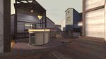
| + | The open and spacious design of Metalworks allow for a, more often than not, [[Glossary#DM|DM]] centric play-style. [[Glossary#Backcap|Backcaps]] are not an uncommon sight, as it is very easy for the aggressive team to fail to lock down all routes. |
| | | | |
| − | Most solids used are engineering materials consisting of crystalline solids in which the atoms or ions are arranged in a repetitive geometric pattern which is known as a [[lattice structure]]. The only exception is material that is made from glass which is a combination of a supercooled liquid and polymers which are aggregates of large organic molecules.<ref name = "Lancaster">{{cite book|last=Lancaster|first=J.F.|title=Metallurgy of welding|year=1999|publisher=Abington Pub.|location=Abington, Cambridge|isbn=1-85573-428-1|edition=6th}}</ref>
| + | In the "cp_metalworks_rc7“ version of Metalworks, there are virtually no hiding spots, save for a couple of exceptions. You are unable to jump on any lamp for example. This separates the cosmetic aspect of the map from the way it is meant to be played, effectively giving the advantage not to the most creative and cunning team, but rather to the most skilful. The collisions of the map have also been scrutinized to prevent Demomen from hiding their sticky-bombs inside brushes or props. |
| | | | |
| − | Crystalline solids cohesion is obtained by a metallic or chemical bond which is formed between the constituent atoms. Chemical bonds can be grouped into two types consisting of [[ionic bond|ionic]] and [[covalent]]. To form an ionic bond, either a [[valence (chemistry)|valence]] or [[chemical bond|bond]]ing electron separates from one atom and becomes attached to another atom to form oppositely charged [[ions]]. The bonding in the static position is when the ions occupy an equilibrium position where the resulting force between them is zero. When the ions are exerted in [[tension (physics)|tension]] force, the inter-ionic spacing increases creating an electrostatic attractive force, while a repulsing force under [[compressive]] force between the atomic nuclei is dominant.<ref name = "Lancaster" />
| + | == Callouts == |
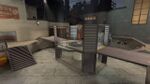
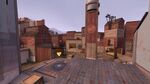
| − | | + | === Mid point === |
| − | Covalent bonding takes place when one of the constituent atoms loses one or more electrons, with the other atom gaining the electrons, resulting in an electron cloud that is shared by the molecule as a whole. In both ionic and covalent bonding the location of the ions and electrons are constrained relative to each other, thereby resulting in the bond being characteristically [[brittle]].<ref name = "Lancaster" />
| + | {{Map locations |
| − | | + | | title = Metalworks mid point callouts |
| − | [[Metallic bonding]] can be classified as a type of covalent bonding for which the constituent atoms of the same type and do not combine with one another to form a chemical bond. Atoms will lose an electron(s) forming an array of positive ions. These electrons are shared by the lattice which makes the electron cluster mobile, as the electrons are free to move as well as the ions. For this, it gives metals their relatively high thermal and electrical conductivity as well as being characteristically [[ductile]].<ref name = "Lancaster" />
| + | | image = Metalworks Middle.jpeg |
| − | | + | | area1 = Valley |
| − | Three of the most commonly used crystal lattice structures in metals are the [[body-centred cubic]], [[face-centred cubic]] and [[close-packing of equal spheres|close-packed hexagonal]]. Ferritic [[steel]] has a body-centred cubic structure and [[austenitic steel]], [[non-ferrous metals]] like [[aluminium|aluminum]], [[copper]] and [[nickel]] have the face-centred cubic structure.<ref name = "Lancaster" />
| + | | x1 = 218px |
| − | | + | | y1 = 170px |
| − | Ductility is an important factor in ensuring the integrity of structures by enabling them to sustain local stress concentrations without fracture. In addition, structures are required to be of an acceptable strength, which is related to a material's [[yield strength]]. In general, as the yield strength of a material increases, there is a corresponding reduction in [[fracture toughness]].<ref name = "Lancaster" />
| + | | area2 = Lower Lobby / Main |
| − | | + | | x2 = 316px |
| − | A reduction in fracture toughness may also be attributed to the embrittlement effect of impurities, or for body-centred cubic metals, from a reduction in temperature. Metals and in particular steels have a transitional temperature range where above this range the metal has acceptable notch-ductility while below this range the material becomes brittle. Within the range, the materials behavior is unpredictable. The reduction in fracture toughness is accompanied by a change in the fracture appearance. When above the transition, the fracture is primarily due to micro-void coalescence, which results in the fracture appearing [[Fiber|fibrous]]. When the temperatures falls the fracture will show signs of cleavage facets. These two appearances are visible by the naked eye. Brittle fracture in steel plates may appear as chevron markings under the [[microscope]]. These arrow-like ridges on the crack surface point towards the origin of the fracture.<ref name = "Lancaster" />
| + | | y2 = 130px |
| − | | + | | area3 = Elbow / Banana |
| − | Fracture toughness is measured using a notched and pre-cracked rectangular specimen, of which the dimensions are specified in standards, for example ASTM E23. There are other means of estimating or measuring fracture toughness by the following: The Charpy impact test per ASTM A370; The crack-tip opening displacement (CTOD) test per BS 7448-1; The J integral test per ASTM E1820; The Pellini drop-weight test per ASTM E208.<ref name = "Lancaster" />
| + | | x3 = 454px |
| − | | + | | y3 = 90px |
| − | ==Unusual conditions== | + | | area4 = Point |
| − | [[File:Working Diver 01.jpg|thumb|left|Underwater welding]]
| + | | x4 = 430px |
| − | | + | | y4 = 180px |
| − | While many welding applications are done in controlled environments such as factories and repair shops, some welding processes are commonly used in a wide variety of conditions, such as open air, underwater, and [[vacuum]]s (such as space). In open-air applications, such as construction and outdoors repair, shielded metal arc welding is the most common process. Processes that employ inert gases to protect the weld cannot be readily used in such situations, because unpredictable atmospheric movements can result in a faulty weld. Shielded metal arc welding is also often used in underwater welding in the construction and repair of ships, offshore platforms, and pipelines, but others, such as flux cored arc welding and gas tungsten arc welding, are also common. Welding in space is also possible—it was first attempted in 1969 by [[Russia]]n cosmonauts, when they performed experiments to test shielded metal arc welding, plasma arc welding, and electron beam welding in a depressurized environment. Further testing of these methods was done in the following decades, and today researchers continue to develop methods for using other welding processes in space, such as laser beam welding, resistance welding, and friction welding. Advances in these areas may be useful for future endeavours similar to the construction of the [[International Space Station]], which could rely on welding for joining in space the parts that were manufactured on Earth.<ref>{{harvnb|Cary|Helzer|2005|pp=677–683}}</ref>
| + | | area5 = Crate |
| − | | + | | x5 = 596px |
| − | ==Safety issues==
| + | | y5 = 150px |
| − | [[Image:AlfredPalmerwelder1.jpg|thumb|Arc welding with a welding helmet, gloves, and other protective clothing]]
| + | | area6 = Upper larry / Balcony |
| − | | + | | x6 = 527px |
| − | Welding can be dangerous and unhealthy if the proper precautions are not taken. However, using new technology and proper protection greatly reduces risks of injury and death associated with welding.<ref>ANSI/AWS Z49.1: "Safety in Welding, Cutting, and Allied Processes" (2005)</ref> Since many common welding procedures involve an open electric arc or flame, the risk of burns and fire is significant; this is why it is classified as a [[hot work]] process. To prevent injury, [[welder]]s wear [[personal protective equipment]] in the form of heavy [[leather]] [[glove]]s and protective long-sleeve jackets to avoid exposure to extreme heat and flames. Additionally, the brightness of the weld area leads to a condition called [[arc eye]] or flash burns in which ultraviolet light causes inflammation of the [[cornea]] and can burn the [[retina]]s of the eyes. [[Goggle]]s and [[welding helmet]]s with dark UV-filtering face plates are worn to prevent this exposure. Since the 2000s, some helmets have included a face plate which instantly darkens upon exposure to the intense UV light. To protect bystanders, the welding area is often surrounded with translucent welding curtains. These curtains, made of a [[polyvinyl chloride]] plastic film, shield people outside the welding area from the UV light of the electric arc, but can not replace the [[filter (optics)|filter]] glass used in helmets.<ref>{{harvnb|Cary|Helzer|2005|pp=42, 49–51}}</ref>
| + | | y6 = 330px |
| − | | + | | area7 = Truck |
| − | [[File:Chamber for Welding Fumes (8743403735).jpg|thumb|left|A chamber designed to contain welding fumes for analysis]]
| + | | x7 = 700px |
| − | [[File:Welding Helmet Effects on Breathing Zone Exposures.webm|thumb|A video describing research on welding helmets and their ability to limit fume exposure]]
| + | | y7 = 182px |
| − | Welders are often exposed to dangerous gases and [[Particle|particulate]] matter. Processes like flux-cored arc welding and shielded metal arc welding produce [[smoke]] containing particles of various types of [[oxide]]s. The size of the particles in question tends to influence the [[toxicity]] of the fumes, with smaller particles presenting a greater danger. This is because smaller particles have the ability to cross the [[blood brain barrier]]. Fumes and gases, such as carbon dioxide, [[ozone]], and fumes containing [[heavy metals]], can be dangerous to welders lacking proper ventilation and training.<ref name="Cary5262">{{harvnb|Cary|Helzer|2005|pp=52–62}}</ref> Exposure to [[manganese]] welding fumes, for example, even at low levels (<0.2 mg/m<sup>3</sup>), may lead to neurological problems or to damage to the lungs, liver, kidneys, or central nervous system.<ref>[http://www.cdc.gov/niosh/topics/welding/ Welding and Manganese: Potential Neurologic Effects]. The inhalation of nano particles National Institute for Occupational Safety and Health. March 30, 2009.</ref> Nano particles can become trapped in the alveolar macrophages of the lungs and induce pulmonary fibrosis.<ref>{{cite journal|title=The significance of nano particles in particle-induced pulmonary fibrosis|author1=James D Byrne|author2=John A Baugh|journal=McGill Journal of Medicine|date=2008|volume=11|pages=43–50|pmc=2322933|pmid=18523535|issue=1}}</ref> The use of compressed gases and flames in many welding processes poses an explosion and fire risk. Some common precautions include limiting the amount of oxygen in the air, and keeping combustible materials away from the workplace.<ref name="Cary5262" />
| |
| − | | |
| − | ==Costs and trends==
| |
| − | As an industrial process, the cost of welding plays a crucial role in manufacturing decisions. Many different variables affect the total cost, including equipment cost, labor cost, material cost, and [[electric power|energy]] cost.<ref name="Weman18489">Weman, pp. 184–89</ref> Depending on the process, equipment cost can vary, from inexpensive for methods like [[shielded metal arc welding]] and [[oxyfuel welding]], to extremely expensive for methods like laser beam welding and electron beam welding. Because of their high cost, they are only used in high production operations. Similarly, because automation and robots increase equipment costs, they are only implemented when high production is necessary. Labor cost depends on the deposition rate (the rate of welding), the hourly wage, and the total operation time, including time spent fitting, welding, and handling the part. The cost of materials includes the cost of the base and filler material, and the cost of shielding gases. Finally, energy cost depends on arc time and welding power demand.<ref name="Weman18489" />
| |
| − | | |
| − | For manual welding methods, labor costs generally make up the vast majority of the total cost. As a result, many cost-saving measures are focused on minimizing operation time. To do this, welding procedures with high deposition rates can be selected, and weld parameters can be fine-tuned to increase welding speed. Mechanization and automation are often implemented to reduce labor costs, but this frequently increases the cost of equipment and creates additional setup time. Material costs tend to increase when special properties are necessary, and energy costs normally do not amount to more than several percent of the total welding cost.<ref name="Weman18489" />
| |
| − | | |
| − | In recent years, in order to minimize labor costs in high production manufacturing, industrial welding has become increasingly more automated, most notably with the use of robots in resistance spot welding (especially in the automotive industry) and in arc welding. In robot welding, mechanized devices both hold the material and perform the weld<ref>Lincoln Electric, p. 4.5-1</ref> and at first, spot welding was its most common application, but robotic arc welding increases in popularity as technology advances. Other key areas of research and development include the welding of dissimilar materials (such as steel and aluminum, for example) and new welding processes, such as friction stir, magnetic pulse, conductive heat seam, and laser-hybrid welding. Furthermore, progress is desired in making more specialized methods like laser beam welding practical for more applications, such as in the aerospace and automotive industries. Researchers also hope to better understand the often unpredictable properties of welds, especially microstructure, [[residual stress]]es, and a weld's tendency to crack or deform.<ref name="ASM International">{{Cite book
| |
| − | | author = ASM International | |
| − | | year = 2003
| |
| − | | title = Trends in Welding Research
| |
| − | | location = Materials Park, Ohio
| |
| − | | publisher = ASM International
| |
| − | | isbn = 0-87170-780-2 | pages=995–1005
| |
| − | }}</ref>
| |
| − | | |
| − | The trend of accelerating the speed at which welds are performed in the [[steel erector|steel erection]] industry comes at a risk to the integrity of the connection. Without proper fusion to the base materials provided by sufficient arc time on the weld, a project inspector cannot ensure the effective diameter of the puddle weld therefore he or she cannot guarantee the published load capacities unless they witness the actual installation.<ref>Gregory L. Snow and W. Samuel Easterling (October 2008) [http://www.us.hilti.com/fstore/holus/LinkFiles/19th_Int_SCCFSS_1.pdf Strength of Arc Spot Welds Made in Single and Multiple Steel Sheets], Proceedings of the 19th International Specialty Conference on Cold-Formed Steel Structures, Missouri University of Science and Technology.</ref> This method of puddle welding is common in the United States and Canada for attaching steel sheets to [[bar joist]] and [[structural steel]] members. Regional agencies are responsible for ensuring the proper installation of puddle welding on steel construction sites. Currently there is no standard or weld procedure which can ensure the published holding capacity of any unwitnessed connection, but this is under review by the [[American Welding Society]].
| |
| − | | |
| − | ==Glass and plastic welding==
| |
| − | [[File:Glass welding two tubes together.JPG|thumb|The welding together of two tubes made from lead glass]]
| |
| − | [[File:Cast glass bowl showing the weld seam.JPG|thumb|A bowl made from cast-glass. The two halves are joined together by the weld seam, running down the middle.]]
| |
| − | | |
| − | Glasses and certain types of plastics are commonly welded materials. Unlike metals, which have a specific [[melting point]], glasses and plastics have a melting range, called the [[glass transition]]. When heating the solid material into this range, it will generally become softer and more pliable. When it crosses through the glass transition, it will become a very thick, sluggish, viscous liquid. Typically, this [[viscous liquid]] will have very little [[surface tension]], becoming a sticky, honey-like consistency, so welding can usually take place by simply pressing two melted surfaces together. The two liquids will generally mix and join at first contact. Upon cooling through the glass transition, the welded piece will solidify as one solid piece of [[amorphous solid|amorphous material]].
| |
| − | | |
| − | ===Glass welding=== | |
| − | {{main article|Glassblowing}}
| |
| − | | |
| − | Glass welding is a common practice during glassblowing. It is used very often in the construction of lighting, [[neon sign]]s, [[flashtube]]s, scientific equipment, and the manufacture of dishes and other glassware. It is also used during [[glass casting]] for joining the halves of glass molds, making items such as bottles and jars. Welding glass is accomplished by heating the glass through the glass transition, turning it into a thick, formable, liquid mass. Heating is usually done with a gas or oxy-gas torch, or a furnace, because the temperatures for melting glass are often quite high. This temperature may vary, depending on the type of glass. For example, [[lead glass]] becomes a weldable liquid at around {{convert|1600|F|C}}, and can be welded with a simple propane torch. On the other hand, quartz glass ([[fused silica]]) must be heated to over {{convert|3000|F|C}}, but quickly loses its viscosity and formability if overheated, so an [[oxyhydrogen]] torch must be used. Sometimes a tube may be attached to the glass, allowing it to be blown into various shapes, such as bulbs, bottles, or tubes. When two pieces of liquid glass are pressed together, they will usually weld very readily. Welding a handle onto a pitcher can usually be done with relative ease. However, when welding a tube to another tube, a combination of blowing and suction, and pressing and pulling is used to ensure a good seal, to shape the glass, and to keep the surface tension from closing the tube in on itself. Sometimes a filler rod may be used, but usually not.
| |
| − | | |
| − | Because glass is very brittle in its solid state, it is often prone to cracking upon heating and cooling, especially if the heating and cooling are uneven. This is because the brittleness of glass does not allow for uneven [[thermal expansion]]. Glass that has been welded will usually need to be cooled very slowly and evenly through the glass transition, in a process called [[annealing (glass)|annealing]], to relieve any internal stresses created by a [[temperature gradient]].
| |
| − | | |
| − | There are many types of glass, and it is most common to weld using the same types. Different glasses often have different rates of thermal expansion, which can cause them to crack upon cooling when they contract differently. For instance, quartz has very low thermal expansion, while [[soda-lime glass]] has very high thermal expansion. When welding different glasses to each other, it is usually important to closely match their coefficients of thermal expansion, to ensure that cracking does not occur. Also, some glasses will simply not mix with others, so welding between certain types may not be possible.
| |
| − | | |
| − | Glass can also be welded to metals and ceramics, although with metals the process is usually more adhesion to the surface of the metal rather than a commingling of the two materials. However, certain glasses will typically bond only to certain metals. For example, lead glass bonds readily to [[copper]] or [[molybdenum]], but not to aluminum. [[Tungsten]] electrodes are often used in lighting but will not bond to quartz glass, so the tungsten is often wetted with molten [[borosilicate glass]], which bonds to both tungsten and quartz. However, care must be taken to ensure that all materials have similar coefficients of thermal expansion to prevent cracking both when the object cools and when it is heated again. Special [[alloy]]s are often used for this purpose, ensuring that the coefficients of expansion match, and sometimes thin, metallic coatings may be applied to a metal to create a good bond with the glass.<ref>Freek Bos, Christian Louter, Fred Veer (2008) ''Challenging Glass: Conference on Architectural and Structural Applications''. JOS Press. p. 194. {{ISBN|1586038664}}</ref><ref>Bernard D. Bolas (1921) [https://archive.org/details/handbookoflabora02bolarich ''A handbook of laboratory glassblowing'']. London, G. Routledge and sons</ref>
| |
| − | | |
| − | ===Plastic welding===
| |
| − | {{main article|Plastic welding}}
| |
| − | | |
| − | Plastics are generally divided into two categories, which are "thermosets" and "thermoplastics." A [[thermoset]] is a plastic in which a chemical reaction sets the molecular bonds after first forming the plastic, and then the bonds cannot be broken again without degrading the plastic. Thermosets cannot be melted, therefore, once a thermoset has set it is impossible to weld it. Examples of thermosets include [[epoxy|epoxies]], [[silicone]], [[vulcanized rubber]], [[polyester]], and [[polyurethane]].
| |
| − | | |
| − | [[Thermoplastic]]s, by contrast, form long molecular chains, which are often coiled or intertwined, forming an amorphous structure without any long-range, crystalline order. Some thermoplastics may be fully amorphous, while others have a partially crystalline/partially amorphous structure. Both amorphous and semicrystalline thermoplastics have a glass transition, above which welding can occur, but semicrystallines also have a specific melting point which is above the glass transition. Above this melting point, the viscous liquid will become a free-flowing liquid (see [[rheological weldability]] for [[thermoplastics]]). Examples of thermoplastics include [[polyethylene]], [[polypropylene]], [[polystyrene]], [[polyvinylchloride]] (PVC), and fluoroplastics like [[Teflon]] and [[Spectralon]].
| |
| − | | |
| − | Welding thermoplastic is very similar to welding glass. The plastic first must be cleaned and then heated through the glass transition, turning the weld-interface into a thick, viscous liquid. Two heated interfaces can then be pressed together, allowing the molecules to mix through intermolecular diffusion, joining them as one. Then the plastic is cooled through the glass transition, allowing the weld to solidify. A filler rod may often be used for certain types of joints. The main differences between welding glass and plastic are the types of heating methods, the much lower melting temperatures, and the fact that plastics will burn if overheated. Many different methods have been devised for heating plastic to a weldable temperature without burning it. Ovens or electric heating tools can be used to melt the plastic. Ultrasonic, laser, or friction heating are other methods. Resistive metals may be implanted in the plastic, which respond to induction heating. Some plastics will begin to burn at temperatures lower than their glass transition, so welding can be performed by blowing a heated, inert gas onto the plastic, melting it while, at the same time, shielding it from oxygen.<ref>''Plastics and Composites: Welding Handbook'' By David A. Grewell, A. Benatar, Joon Bu Park – Hanser Gardener 2003</ref>
| |
| − | | |
| − | Many thermoplastics can also be welded using chemical [[solvent]]s. When placed in contact with the plastic, the solvent will begin to soften it, bringing the surface into a thick, liquid solution. When two melted surfaces are pressed together, the molecules in the solution mix, joining them as one. Because the solvent can permeate the plastic, the solvent evaporates out through the surface of the plastic, causing the weld to drop out of solution and solidify. A common use for solvent welding is for joining PVC or ABS ([[acrylonitrile butadiene styrene]]) pipes during [[plumbing]], or for welding [[styrene]] and polystyrene plastics in the construction of [[physical model|models]]. Solvent welding is especially effective on plastics like PVC which burn at or below their glass transition, but may be ineffective on plastics like Teflon or polyethylene that are resistant to [[chemical decomposition]].<ref>''Handbook of Plastics Joining: A Practical Guide'' By Plastics Design Library – PDL 1997 Page 137, 146</ref>
| |
| − | | |
| − | ==See also==
| |
| − | *[[List of welding codes]]
| |
| − | *[[List of welding processes]]
| |
| − | *[[Regulated Metal Deposition]]
| |
| − | *[[Welding Procedure Specification]]
| |
| − | *[[Welder certification]]
| |
| − | *[[Welded sculpture]]
| |
| − | | |
| − | ==Notes==
| |
| − | {{Reflist|30em}}
| |
| − | | |
| − | ==References==
| |
| − | *{{Cite book
| |
| − | | last = Cary
| |
| − | | first = Howard B
| |
| − | | first2=Scott C. |last2=Helzer
| |
| − | | year = 2005
| |
| − | | title = Modern Welding Technology
| |
| − | | location = Upper Saddle River, [[New Jersey]]
| |
| − | | publisher = Pearson Education
| |
| − | | isbn = 0-13-113029-3
| |
| − | | ref=harv
| |
| − | }}
| |
| − | *{{Cite book
| |
| − | | last = Kalpakjian
| |
| − | | first = Serope
| |
| − | |author2=Steven R. Schmid
| |
| − | | year = 2001
| |
| − | | title = Manufacturing Engineering and Technology
| |
| − | | publisher = Prentice Hall
| |
| − | | isbn = 0-201-36131-0
| |
| | }} | | }} |
| − | *{{Cite book
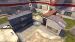
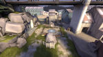
| + | === Second point === |
| − | | author = Lincoln Electric
| + | {{Map locations |
| − | | year = 1994
| + | | title = Metalworks second point callouts |
| − | | title = The Procedure Handbook of Arc Welding
| + | | image = Metalworks Second.jpeg |
| − | | location = [[Cleveland]]
| + | | area1 = Underpass / Ground |
| − | | publisher = Lincoln Electric
| + | | x1 = 390px |
| − | | isbn = 99949-25-82-2
| + | | y1 = 170px |
| − | | authorlink = Lincoln Electric
| + | | area2 = Alleyway |
| | + | | x2 = 637px |
| | + | | y2 = 200px |
| | + | | area3 = Main / Metal |
| | + | | x3 = 388px |
| | + | | y3 = 125px |
| | + | | area4 = Point |
| | + | | x4 = 283px |
| | + | | y4 = 244px |
| | + | | area5 = Bridge |
| | + | | x5 = 247px |
| | + | | y5 = 179px |
| | }} | | }} |
| − | *{{Cite book
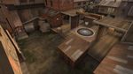
| + | === Last point === |
| − | | last = Weman
| + | {{Map locations |
| − | | first = Klas
| + | | title = Metalworks last point callouts |
| − | | year = 2003
| + | | image = Metalworks Last.jpeg |
| − | | title = Welding processes handbook
| + | | area1 = Far Left |
| − | | location = New York, NY
| + | | x1 = 131px |
| − | | publisher = CRC Press LLC
| + | | y1 = 170px |
| − | | isbn = 0-8493-1773-8
| + | | area2 = Shed |
| | + | | x2 = 177px |
| | + | | y2 = 121px |
| | + | | area3 = Shutter |
| | + | | x3 = 330px |
| | + | | y3 = 80px |
| | + | | area4 = Main |
| | + | | x4 = 402px |
| | + | | y4 = 68px |
| | + | | area5 = Far Right |
| | + | | x5 = 612px |
| | + | | y5 = 102px |
| | }} | | }} |
| | | | |
| − | ==External links==
| |
| − | {{Commons|Welding}}
| |
| − | *{{dmoz|Science/Technology/Welding}}
| |
| | | | |
| − | {{Metalworking navbox|weldopen}} | + | == Map information == |
| − | {{Machine and metalworking tools}} | + | {{Box|start|padding=2em}} |
| | + | {| class="wikitable" width="300px" style="text-align:center" |
| | + | |+ Point capture times (seconds) |
| | + | ! Multiplier |
| | + | ! [[Glossary#Mid|Mid]] |
| | + | ! [[Glossary#Second|Second]] |
| | + | ! [[Glossary#Last|Last]] |
| | + | |- |
| | + | ! x1 |
| | + | | 20.00 |
| | + | | 16.00 |
| | + | | 4.00 |
| | + | |- |
| | + | ! x2 |
| | + | | 13.33 |
| | + | | 10.67 |
| | + | | 2.67 |
| | + | |- |
| | + | ! x3 |
| | + | | 10.91 |
| | + | | 8.73 |
| | + | | 2.18 |
| | + | |- |
| | + | ! x4 |
| | + | | 9.60 |
| | + | | 7.68 |
| | + | | 1.92 |
| | + | |- |
| | + | ! x5 |
| | + | | 8.76 |
| | + | | 7.01 |
| | + | | 1.75 |
| | + | |- |
| | + | ! x6 |
| | + | | 8.16 |
| | + | | 6.53 |
| | + | | 1.63 |
| | + | |- |
| | + | ! x7 |
| | + | | 7.71 |
| | + | | 6.17 |
| | + | | 1.54 |
| | + | |- |
| | + | ! x8 |
| | + | | 7.36 |
| | + | | 5.89 |
| | + | | 1.47 |
| | + | |- |
| | + | ! x9 |
| | + | | 7.07 |
| | + | | 5.66 |
| | + | | 1.41 |
| | + | |- |
| | + | ! x10 |
| | + | | 6.83 |
| | + | | 5.46 |
| | + | | 1.37 |
| | + | |- |
| | + | ! x11 |
| | + | | 6.62 |
| | + | | 5.30 |
| | + | | 1.32 |
| | + | |} |
| | + | {{Box|break|padding=2em}} |
| | + | {| class="wikitable" width="300px" style="text-align:center" |
| | + | |+ Respawn wave times (seconds) |
| | + | ! colspan=5 | Control points owned by opposing team |
| | + | |- |
| | + | ! 1 |
| | + | ! 2 |
| | + | ! Neutral |
| | + | ! 3 |
| | + | ! 4 |
| | + | |- |
| | + | | 7 |
| | + | | 10 |
| | + | | 10 |
| | + | | 10 |
| | + | | 10 |
| | + | |} |
| | + | {{Box|break}} |
| | + | {| class="wikitable" width="300px" style="text-align:center" |
| | + | |+ Health and ammo packs |
| | + | ! [[File:Smallhealth.png|20px|Small health|link=]] |
| | + | ! [[File:Mediumhealth.png|20px|Medium health|link=]] |
| | + | ! [[File:Smallammo.png|20px|Small ammo|link=]] |
| | + | ! [[File:Mediumammo.png|20px|Medium ammo|link=]] |
| | + | |- |
| | + | | 4 |
| | + | | 8 |
| | + | | 4 |
| | + | | 12 |
| | + | |} |
| | + | {{Box|end}} |
| | | | |
| − | {{Authority control}} | + | == Map pool history == |
| | + | {| class="wikitable emptycells-gray mw-collapsible" style="text-align:center" |
| | + | |+ style="white-space:nowrap" | Metalworks map pool history |
| | + | |- |
| | + | ! {{abbr|DL|Download link}} |
| | + | ! Map version |
| | + | ! style="width:120px" | Asia |
| | + | ! style="width:120px" | Europe |
| | + | ! style="width:120px" | North America |
| | + | ! style="width:120px" | Oceania |
| | + | |- |
| | + | ! rowspan=3 | {{download|https://dl.serveme.tf/maps/cp_metalworks_f4.bsp}} |
| | + | ! style="text-align:left; font-weight:normal" rowspan=3 | <code>cp_metalworks_f4</code> |
| | + | | |
| | + | | {{LeagueIconSmall|etf2l}} [[ETF2L 6v6 Season 42|Season 42]] |
| | + | | {{LeagueIconSmall|rgl}} [[RGL Traditional Sixes Season 10|Season 10]] |
| | + | | |
| | + | |- |
| | + | | |
| | + | | |
| | + | | {{LeagueIconSmall|rgl}} [[RGL Traditional Sixes Season 9|Season 9]] |
| | + | | |
| | + | |- |
| | + | | |
| | + | | |
| | + | | {{LeagueIconSmall|rgl}} [[RGL Traditional Sixes Season 8|Season 8]] |
| | + | | |
| | + | |- |
| | + | ! {{download|https://dl.serveme.tf/maps/cp_metalworks_f2.bsp}} |
| | + | ! style="text-align:left; font-weight:normal" | <code>cp_metalworks_f2</code> |
| | + | | |
| | + | | {{LeagueIconSmall|etf2l}} [[ETF2L 6v6 Season 41|Season 41]] |
| | + | | |
| | + | | |
| | + | |- |
| | + | ! {{download|https://dl.serveme.tf/maps/cp_metalworks_f1.bsp}} |
| | + | ! style="text-align:left; font-weight:normal" | <code>cp_metalworks_f1</code> |
| | + | | {{LeagueIconSmall|af}} [[AsiaFortress Cup 19|Cup 19]] |
| | + | | |
| | + | | |
| | + | | |
| | + | |- |
| | + | ! rowspan=15 | |
| | + | ! style="text-align:left; font-weight:normal" rowspan=15 | <code>cp_metalworks</code> |
| | + | | |
| | + | | {{LeagueIconSmall|etf2l}} [[ETF2L 6v6 Season 40|Season 40]] |
| | + | | {{LeagueIconSmall|rgl}} [[RGL Traditional Sixes Season 7|Season 7]] |
| | + | | {{LeagueIconSmall|ozf}} [[OZF 32]] |
| | + | |- |
| | + | | |
| | + | | {{LeagueIconSmall|etf2l}} [[ETF2L 6v6 Season 38|Season 38]] |
| | + | | {{LeagueIconSmall|rgl}} [[RGL Traditional Sixes Season 6|Season 6]] |
| | + | | {{LeagueIconSmall|ozf}} [[OZF 31]] |
| | + | |- |
| | + | | |
| | + | | {{LeagueIconSmall|etf2l}} [[ETF2L 6v6 Season 37|Season 37]] |
| | + | | {{LeagueIconSmall|rgl}} [[RGL Traditional Sixes Season 5|Season 5]] |
| | + | | {{LeagueIconSmall|ozf}} [[OZF 30]] |
| | + | |- |
| | + | | |
| | + | | {{LeagueIconSmall|etf2l}} [[ETF2L 6v6 Season 36|Season 36]] |
| | + | | {{LeagueIconSmall|rgl}} [[RGL Traditional Sixes Season 4|Season 4]] |
| | + | | {{LeagueIconSmall|ozf}} [[OZF 29]] |
| | + | |- |
| | + | | |
| | + | | {{LeagueIconSmall|etf2l}} [[ETF2L 6v6 Season 33|Season 33]] |
| | + | | {{LeagueIconSmall|rgl}} [[RGL Traditional Sixes Season 3|Season 3]] |
| | + | | {{LeagueIconSmall|ozf}} [[OZF 28]] |
| | + | |- |
| | + | | |
| | + | | |
| | + | | {{LeagueIconSmall|rgl}} [[RGL Traditional Sixes Season 2|Season 2]] |
| | + | | {{LeagueIconSmall|ozf}} [[OZF 24]] |
| | + | |- |
| | + | | |
| | + | | |
| | + | | {{LeagueIconSmall|rgl}} [[RGL Traditional Sixes Season 1|Season 1]] |
| | + | | |
| | + | |- |
| | + | | |
| | + | | |
| | + | | {{LeagueIconSmall|esea}} [[ESEA-I Season 31|Season 31]] |
| | + | | |
| | + | |- |
| | + | | |
| | + | | |
| | + | | {{LeagueIconSmall|esea}} [[ESEA-I Season 30|Season 30]] |
| | + | | |
| | + | |- |
| | + | | |
| | + | | |
| | + | | {{LeagueIconSmall|esea}} [[ESEA-I Season 29|Season 29]] |
| | + | | |
| | + | |- |
| | + | | |
| | + | | |
| | + | | {{LeagueIconSmall|esea}} [[ESEA-I Season 28|Season 28]] |
| | + | | |
| | + | |- |
| | + | | |
| | + | | |
| | + | | {{LeagueIconSmall|esea}} [[ESEA-I Season 27|Season 27]] |
| | + | | |
| | + | |- |
| | + | | |
| | + | | |
| | + | | {{LeagueIconSmall|esea}} [[ESEA-I Season 26|Season 26]] |
| | + | | |
| | + | |- |
| | + | | |
| | + | | |
| | + | | {{LeagueIconSmall|esea}} [[ESEA-I Season 25|Season 25]] |
| | + | | |
| | + | |- |
| | + | | |
| | + | | |
| | + | | {{LeagueIconSmall|esea}} [[ESEA-I Season 24|Season 24]] |
| | + | | |
| | + | |- |
| | + | ! rowspan=5 | {{download|https://dl.serveme.tf/maps/cp_metalworks_rc7.bsp}} |
| | + | ! style="text-align:left; font-weight:normal" rowspan=5 | <code>cp_metalworks_rc7</code> |
| | + | | {{LeagueIconSmall|af}} [[AsiaFortress Cup 9|Cup 9]] |
| | + | | |
| | + | | {{LeagueIconSmall|esea}} [[ESEA-I Season 23|Season 23]] |
| | + | | |
| | + | |- |
| | + | | |
| | + | | |
| | + | | {{LeagueIconSmall|esea}} [[ESEA-I Season 22|Season 22]] |
| | + | | |
| | + | |- |
| | + | | |
| | + | | |
| | + | | {{LeagueIconSmall|esea}} [[ESEA-I Season 21|Season 21]] |
| | + | | |
| | + | |- |
| | + | | |
| | + | | |
| | + | | {{LeagueIconSmall|esea}} [[ESEA-I Season 20|Season 20]] |
| | + | | |
| | + | |- |
| | + | | |
| | + | | |
| | + | | {{LeagueIconSmall|esea}} [[ESEA-I Season 19|Season 19]] |
| | + | | |
| | + | |- |
| | + | ! rowspan=4 | {{download|https://dl.serveme.tf/maps/cp_metalworks_rc5.bsp}} |
| | + | ! style="text-align:left; font-weight:normal" rowspan=4 | <code>cp_metalworks_rc5</code> |
| | + | | {{LeagueIconSmall|af}} [[AsiaFortress Cup 8|Cup 8]] |
| | + | | {{LeagueIconSmall|etf2l}} [[ETF2L 6v6 Season 17|Season 17]] |
| | + | | {{LeagueIconSmall|esea}} [[ESEA-I Season 18|Season 18]] |
| | + | | {{LeagueIconSmall|ozf}} [[OWL 11]] |
| | + | |- |
| | + | | |
| | + | | {{LeagueIconSmall|etf2l}} [[ETF2L 6v6 Season 16|Season 16]] |
| | + | | {{LeagueIconSmall|esea}} [[ESEA-I Season 17|Season 17]] |
| | + | | {{LeagueIconSmall|ozf}} [[OZF 10]] |
| | + | |- |
| | + | | |
| | + | | |
| | + | | {{LeagueIconSmall|esea}} [[ESEA-I Season 16|Season 16]] |
| | + | | |
| | + | |- |
| | + | | |
| | + | | |
| | + | | {{LeagueIconSmall|esea}} [[ESEA-I Season 15|Season 15]] |
| | + | | |
| | + | |- |
| | + | ! [[File:Download icon.png|20px|link=https://rotabland.eu/maps/map.php?id=5486&type=0]] |
| | + | ! style="text-align:left; font-weight:normal" | <code>cp_metalworks_rc4</code> |
| | + | | {{LeagueIconSmall|af}} [[AsiaFortress Cup 7|Cup 7]] |
| | + | | |
| | + | | {{LeagueIconSmall|esea}} [[ESEA-I Season 14|Season 14]] |
| | + | | |
| | + | |- |
| | + | ! [[File:Download icon.png|20px|link=https://rotabland.eu/maps/map.php?id=4549&type=0]] |
| | + | ! style="text-align:left; font-weight:normal" | <code>cp_metalworks_rc3</code> |
| | + | | |
| | + | | |
| | + | | {{LeagueIconSmall|esea}} [[ESEA-I Season 13|Season 13]] |
| | + | | |
| | + | |} |
| | | | |
| − | [[Category:Welding| ]]
| + | == References == |
| − | [[Category:IARC Group 2B carcinogens]]
| + | {{reflist}} |
| − | [[Category:Articles containing video clips]]
| |
| − | [[Category:Joining]]
| |
| − | [[Category:Mechanical engineering]]
| |
| | | | |
| − | == Jim Vickers rating ==
| + | {{Navbox/6v6 maps}} |
| − | 1/5 Jims
| |
| − | {{Active Maps Navbox}}{{All Maps Navbox|y}} | |